
Patellar Tracking in TKA
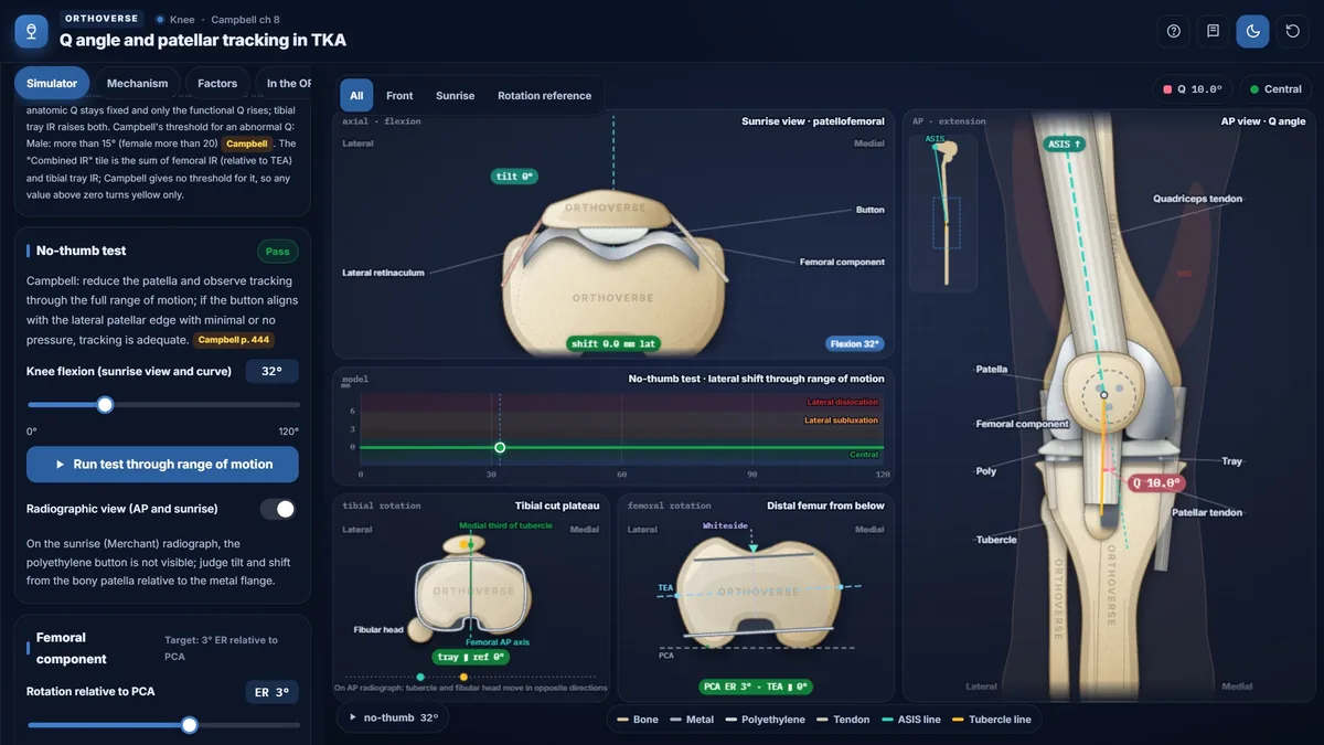
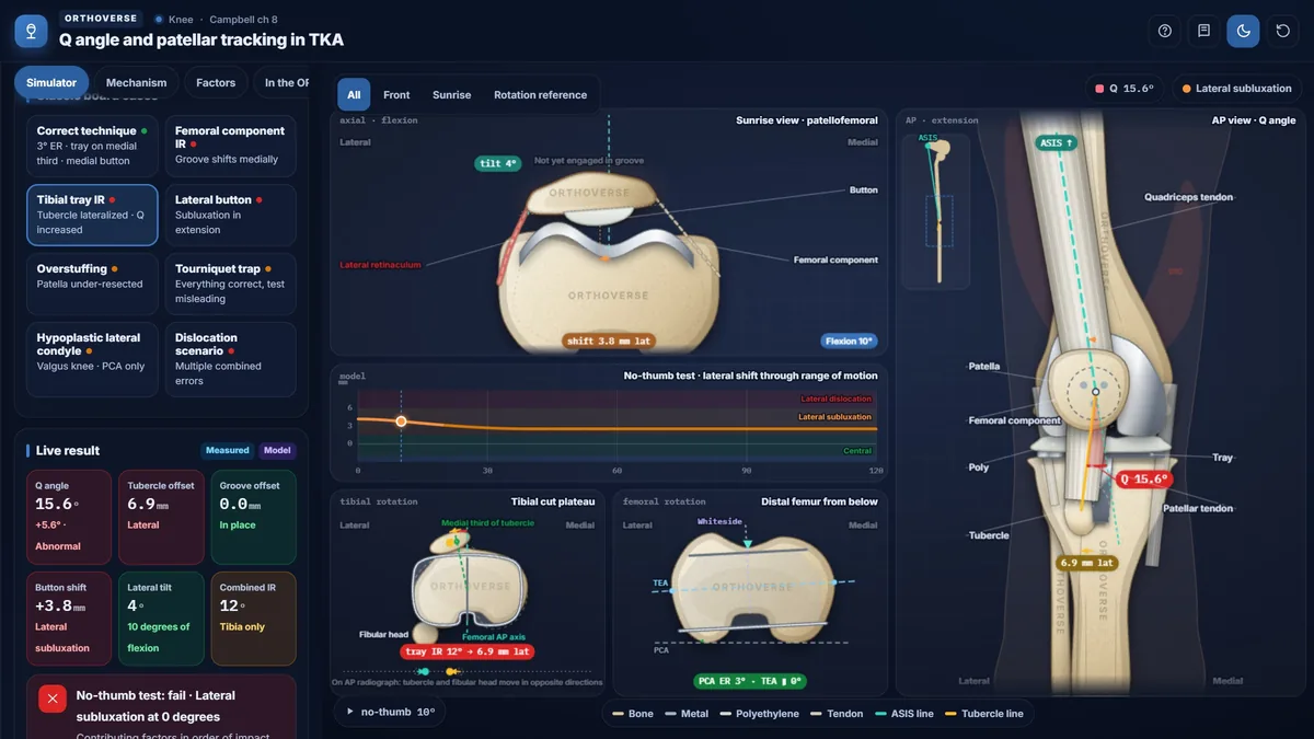
Rotate the femoral and tibial components, move the patellar button and flex the knee: the Q angle, patellar tilt and shift and the no-thumb test respond live in the sunrise and AP views.
What you can do
- See one knee model in four linked views: sunrise, AP, the tibial cut surface and the distal femur from below.
- Flex the knee from 0° to 120° and run the no-thumb test through the whole range of motion.
- Rotate the femoral component against the PCA and TEA, and the tibial tray against the tubercle.
- Move the patellar button, overstuff the patella and see subluxation appear.
- Load eight classic board cases, from the correct technique to the full dislocation scenario.
- Work through the mechanism, the contributing factors, step-by-step correction in the OR and a quiz.
Key concepts
The Q angle runs from the ASIS to the center of the patella and on to the tibial tubercle. A larger Q angle pulls the patella laterally.
Internal rotation of the femoral component moves the trochlear groove medially, and internal rotation of the tibial tray lateralizes the tubercle; both push the patella toward lateral tracking.
A medialized patellar button and a correctly rotated femoral component (about 3° external rotation to the PCA, parallel to the TEA) protect tracking; the tourniquet can make a good knee test badly.
Teaching notes
Patellar maltracking is a leading cause of anterior knee pain and reoperation after total knee arthroplasty. Understanding how component rotation, button placement, and soft-tissue tension contribute to the lateral force vector allows surgeons to prevent problems intraoperatively and correct them systematically.
The Q Angle
The Q angle is the angle between the line from the anterior superior iliac spine to the center of the patella and the line from the patella to the tibial tubercle. A larger Q angle produces a stronger lateral pull on the patella. The mean Q angle is 10 degrees in men and 15 degrees in women; Campbell defines an abnormal Q as greater than 15 degrees in men and greater than 20 degrees in women. In flexion, the tibia internally rotates relative to the femur, centralizing the tubercle; the Q angle therefore decreases with increasing knee flexion.
How Component Rotation Drives Maltracking
Two distinct mechanisms produce the same result — lateral patellar instability — through different pathways. Internal rotation or medial translation of the femoral component shifts the trochlear groove medially; the tubercle remains in place, so the patella lies lateral to the groove. The anatomic Q angle is unchanged because the ASIS-to-tubercle geometry has not moved, but the functional Q angle rises.
Internal rotation of the tibial tray acts differently: because the articular surface of the tray must couple with the femoral component, the tibial bone itself rotates externally by the same amount. The tibial tubercle, lying anterior to the center of rotation, moves laterally, raising both the anatomic and functional Q angles.
- Femoral component target: 3 degrees external rotation from the posterior condylar axis, parallel to the transepicondylar axis, perpendicular to the Whiteside line.
- In a valgus knee with a small lateral condyle, relying solely on the posterior condylar axis internally rotates the component; cross-reference the transepicondylar axis and the Whiteside line.
- Tibial tray: center over the medial one-third of the tubercle; if any deviation is made, err toward slight external rotation.
Patellar Button Placement and Thickness
The button should be placed medially at the natural median ridge, not at the center of the resected surface. Central placement shifts the bony patella medially, raising the functional Q angle; lateral placement causes subluxation in extension. Overstuffing anteriorizes the patella, tightens the retinaculum, and limits flexion. Because of the natural asymmetry of the facets, the lateral facet generally requires considerably less resection than the medial; excessive lateral resection produces component tilt. Leaving less than 10 to 15 mm of residual patellar bone increases the risk of intraoperative fracture.
Intraoperative Assessment and the Tourniquet Trap
The no-thumb test is performed by reducing the patella in the groove and observing tracking through the full range of motion without applying thumb pressure to the lateral patellar edge. A critical trap: the inflated tourniquet tightens the extensor mechanism and can make an otherwise acceptable knee appear to track poorly. Campbell found that in 48 percent of knees initial maltracking normalized after tourniquet release, and in another series 31 percent did not ultimately require a lateral release. Always deflate the tourniquet and reassess before concluding that any soft-tissue procedure is needed.
Treatment Sequence When the Patella Still Subluxes
Component rotation and position, button placement, and patellar thickness must be confirmed correct before any soft-tissue procedure is considered. Lateral retinacular release is indicated only when components are correctly positioned and the patella still subluxes; it is rarely sufficient on its own. The release extends from Gerdy's tubercle to the fibers of vastus lateralis; the greatest risk is devascularization of the patella from division of the superior lateral geniculate artery.
If subluxation persists after release, proximal realignment is the next step. Distal realignment by tibial tubercle osteotomy is reserved for extreme cases: nonunion causes severe functional loss, and additional risks include proximal tibial fracture and stress fracture at the osteotomy site.
Try this in the simulator
- Set the femoral component to internal rotation using the rotation slider and observe how the groove shifts medially in the sunrise view and the functional Q angle rises without any change to the anatomic Q angle.
- Apply tibial tray internal rotation and compare the result: watch the tubercle move laterally on the AP view and note that both the anatomic and functional Q angles increase.
- Move the patellar button from the medial position to central or lateral using the 'Button position on the resected surface' control and run the no-thumb test to see how button placement alone can cause subluxation.
- Load the tourniquet trap preset — all components correct, tourniquet inflated — confirm the no-thumb test appears to fail, then release the tourniquet to see tracking normalize.
- Load the dislocation scenario and use the step-by-step 'In the OR' correction controls to work through each contributing factor in the order a surgeon would address them.
Pitfalls
- Performing a lateral retinacular release before releasing the tourniquet and reassessing: up to 48 percent of apparent maltracking resolves after tourniquet deflation alone.
- Referencing only the posterior condylar axis in a valgus knee with a hypoplastic lateral condyle; this systematically internally rotates the femoral component and drives lateral patellar instability.
- Centering the patellar button on the resected surface rather than placing it medially at the median ridge; this raises the functional Q angle and predisposes to subluxation.
- Overlooking tibial tray internal rotation as a cause of elevated Q angle: the tibia rotates externally and the tubercle moves laterally, raising the anatomic Q angle visible on the AP radiograph.
- Proceeding to tibial tubercle osteotomy without first correcting component position and attempting lateral release and proximal realignment; tubercle nonunion is a functionally catastrophic outcome.
One-page high-yield card
The key facts, numbers and pitfalls of this simulator on one printable page. Free for personal study.
Further reading
- Campbell's Operative Orthopaedics, 15th edition (2026): Arthroplasty of the Knee, ch 8 (Q angle, component rotation and patellar tracking).

Designed for Orthoverse by Dr. M. M. Bakhshaei. Built to make orthopedic concepts visible, measurable and easy to explore.
Have an idea for the next simulator?
Tell us which concept you would like to explore. Message our bot and we will read every idea.
For medical education only. Orthoverse simulators are teaching models for health professionals and students. They are simplified on purpose, are not medical devices and are not a substitute for clinical judgement, patient-specific imaging or the original literature.
© 2026 Orthoverse. All rights reserved. The simulators, their code, drawings and models are original work. Free to use for learning on orthoverse.org; copying, embedding, scraping or redistribution is not permitted. Textbook references are cited for further reading only.